


Your Rogers PCB Manufacturer in China
- Structure Capability: Multilayer, mixed-lamination, blind/buried vias, and HDI for high-frequency designs.
- Tolerance Control: ±0.10 mm dimensional tolerance and minimum 0.8 mil line width/spacing.
- Dk Capability: Dk range of 2.2–10.2 for antennas, filters, and RF circuits.
- Moisture Resistance: 0.02%–0.10% water absorption for stable performance in humid conditions.
- Quality Testing: 100% E-testing, AOI, and flying probe inspection.
- Certification: ISO 9001, ISO 14001, UL, and RoHS compliance.
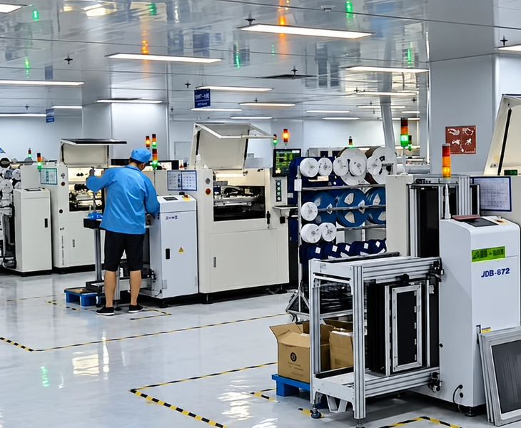
What is a Rogers PCB?
Rogers PCB is a high-frequency printed circuit board manufactured utilizing advanced Rogers dielectric materials. Compared to standard PCB materials, it is specifically designed for systems requiring low signal loss, stable dielectric properties, and controlled electrical parameters. These boards are primarily adopted in RF systems, microwaves, radar equipment, and telecommunications equipment.
Consons employs 100% genuine Rogers materials, combined with mature high-frequency PCB manufacturing processes and a complete quality control system, to provide you with customized Rogers PCB solutions. We help you realize mass production of complex high-frequency circuit structures.
Our Types of Rogers PCB
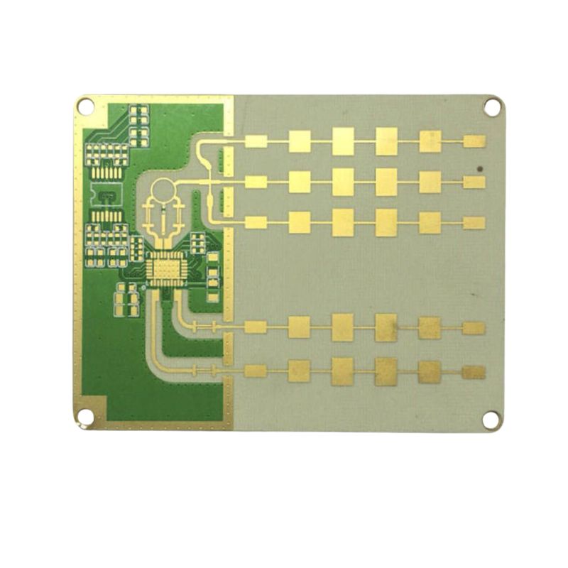
Designed with a high-Tg, low-CTE material system, providing consistent dielectric properties and excellent thermal reliability, ideal for mass production.
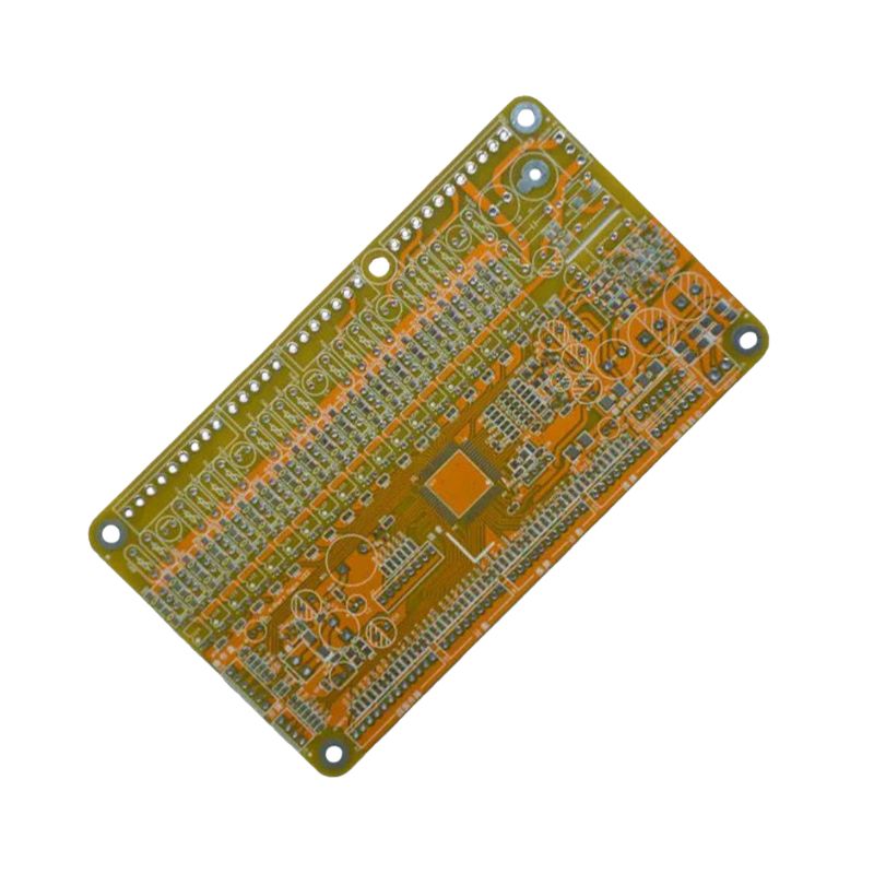
Supporting millimeter-wave design and offering low dielectric loss, suitable for automotive radar, microwave communications, and high-frequency antennas.
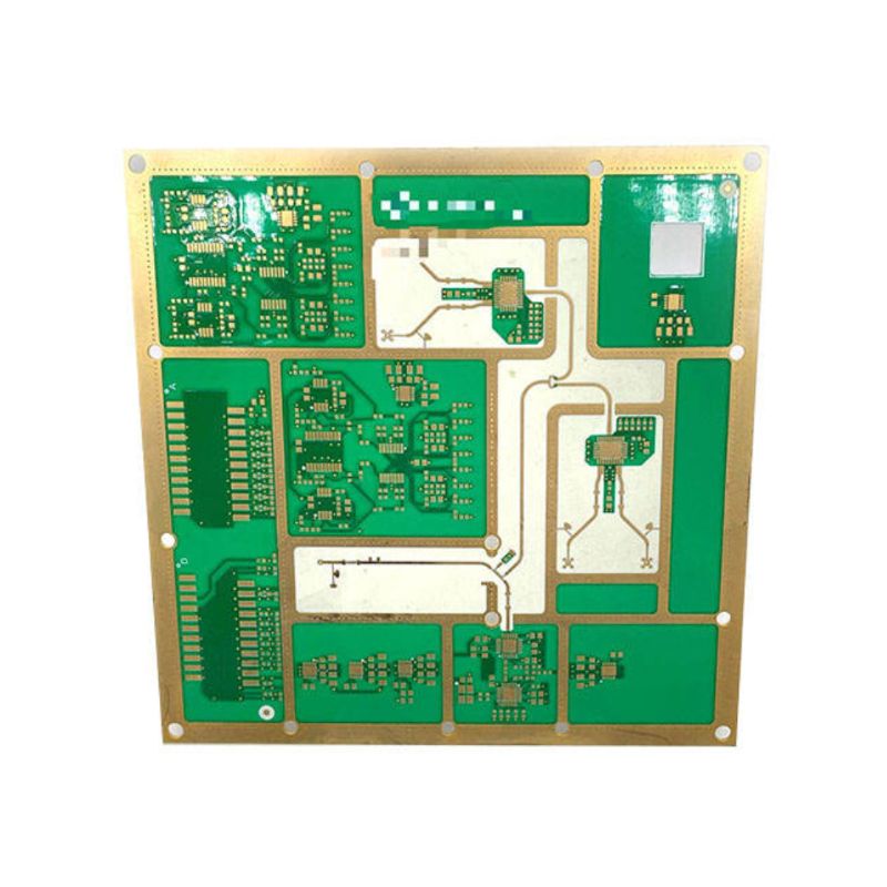
A classic PTFE material with extremely low dielectric loss, enabling high-frequency signals to sustain signal integrity even during long-distance transmission.
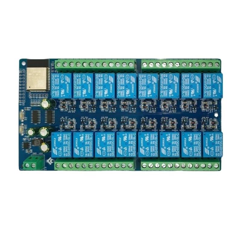
Utilizing a high-performance microwave composite material system, featuring excellent mechanical stability, facilitates the design of complex microwave structures.
Advantages of Rogers PCB

Our Rogers laminate material can control signal loss at a minimum level, providing purer signals and higher efficiency in high-frequency paths.

The consistent Dk/Df control capabilities help decrease the discrepancy of simulated and actual performance to enhance the electrical uniformity of batch products.

We precisely control the PCB layer stack-up, dielectric thickness, copper thickness, and trace width/spacing to guarantee that the design impedance complies with specifications.

By combining controlled lamination and heat treatment processes, Rogers can minimize dimensional changes resulting from temperature fluctuations and improve structural stability.

Using a material system with low outgassing characteristics to comply with the volatility requirements of materials in a vacuum environment.

Rogers materials offer chemical stability and low moisture absorption, minimizing the impact of moisture, chemical environments, and long-term outdoor exposure on PCB performance.
Customized Rogers PCB Stackup Solutions
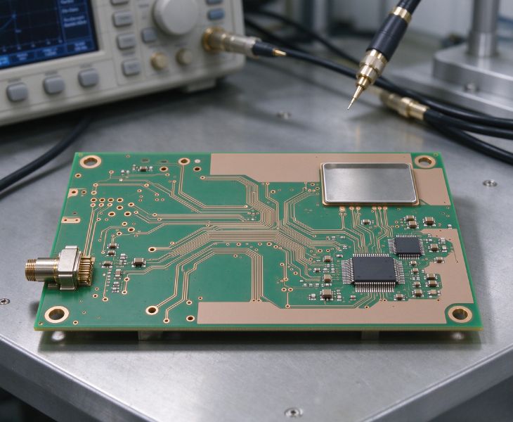
For complex RF designs, using Rogers material across the entire board increases costs. But standard PCB materials can’t satisfy high-frequency performance standards. Consons offers customized Rogers and FR-4 hybrid laminate solutions. We choose the right materials depending on the performance demands of each circuit layer and place high-performance materials in critical areas. This helps your product meet RF performance targets while avoiding unnecessary costs.
Professional Engineering Support for Rogers PCB Projects
When developing Rogers PCBs, Consons provides end-to-end engineering support, covering material selection, layer stackup design, impedance modeling, Dk/Df matching, and DFM evaluation. We help you optimize your Rogers PCB design before production, reduce the number of design revisions and improve efficiency in the development process, which accelerates the process from design verification to mass production.
Why Choose Consons As Your Rogers PCB Partner?
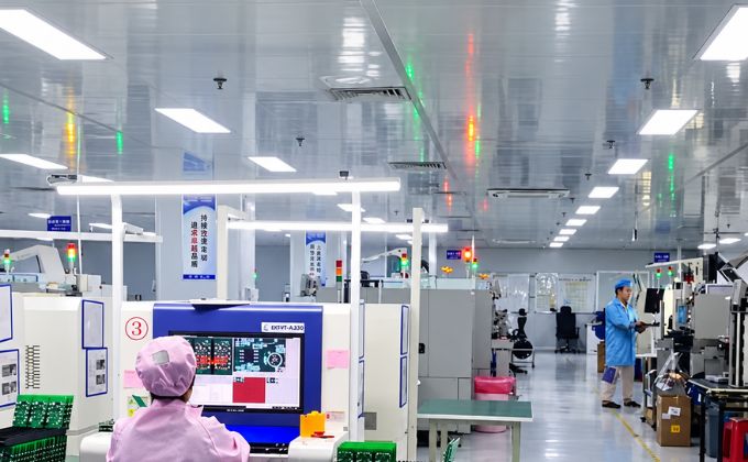
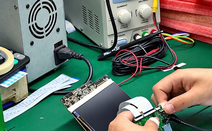
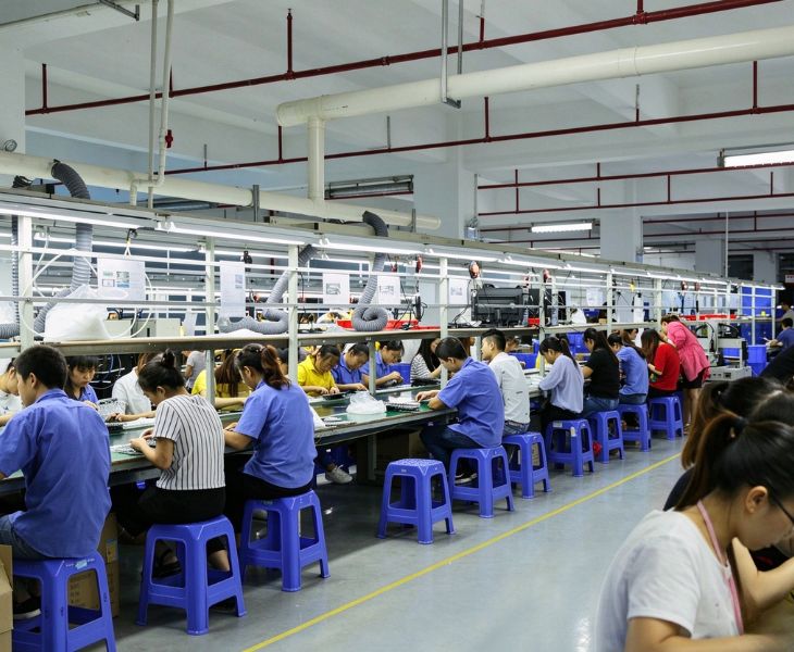
Extensive Manufacturing Experience: With over 20 years of experience in Rogers PCB manufacturing, Consons supports you from prototype validation to high-volume production, helping you quickly achieve PCB project launches.
PCB Assembly Services : We have 15 SMT production lines and 4 DIP production lines, which can provide you with professional Rogers PCB assembly services to help you streamline the supply chain and shorten overall project lead times.
Fast Technical Support: Consons has 35,000 square meters of production facilities and more than 1,600 skilled employees. They can evaluate and handle your Rogers PCB projects rapidly.
Global Delivery Capability: We have worked with more than 40 countries, have ample overseas Rogers PCB project experience, and are familiar with IPC standards, international technical documentation, and export procedures.
Where Are Consons’ Rogers PCBs Applied?

Our Rogers PCBs are made from low-Df Rogers laminates, supporting GHz-level high-frequency signal transmission and remaining reliable even during long-term operation. These boards meet the impedance consistency requirements of antennas and communication equipment.
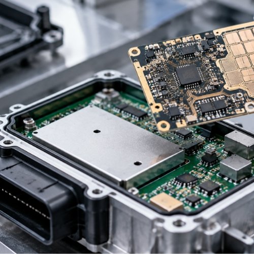
The automotive radar needs accurate millimeter-wave signal control and robust electrical performance to fulfill detection requirements. Consons Rogers series of PCBs utilizes low-loss materials like RO3003 and impedance-controlled manufacturing techniques to support 24 GHz and 77 GHz radar applications.
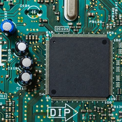
The aerospace and defense electronics fields demand PCBs that can operate in rigorous environments and support complex RF circuit designs. Our Rogers PCBs provide low moisture absorption and steady electrical performance across a wide temperature range, addressing these requirements perfectly.
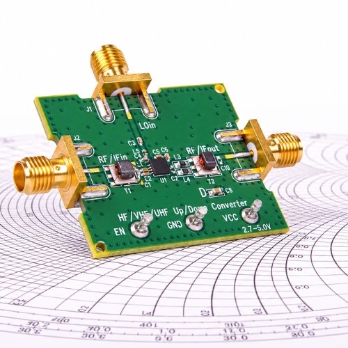
Our Rogers PCBs are designed for RF modules, microwave circuits, filters, power amplifiers, and more. We offer advanced multilayer design capabilities and PTFE-based Rogers PCB manufacturing, guaranteeing reliable high-frequency performance.
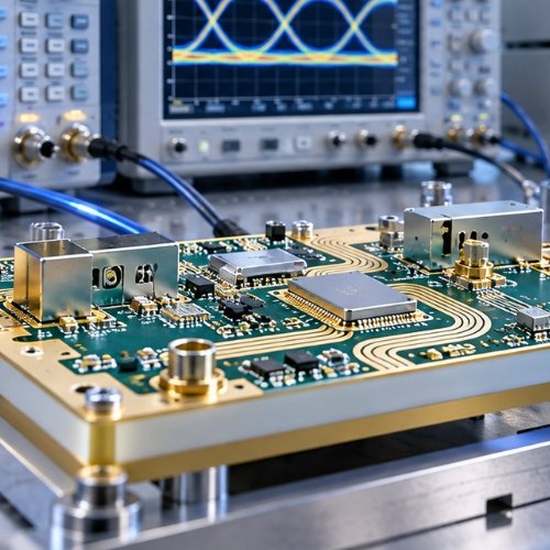
Our Rogers PCBs can also be used in network analyzers, oscilloscopes, and measuring instruments. These PCBs minimize signal distortion in high-frequency circuits, helping measurement systems achieve precise signal analysis and repeatable test results.
Project Cases of Consons Rogers PCB
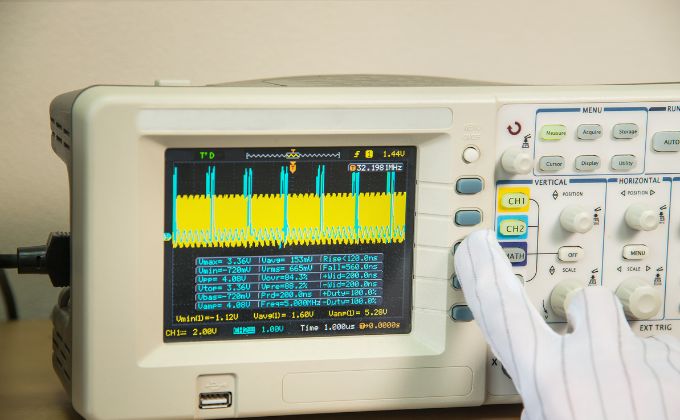
The customer is developing a high-frequency measurement device that requires a PCB material with low signal loss and precise impedance control. Its purpose is to support the transmission of GHz-level signals. During the prototyping phase, the previously used PCB solution exhibited electrical performance instability.
Consons adopted RO4003C material, which features low dielectric loss. We also strictly controlled critical parameters, including dielectric thickness, copper structure, and transmission line design. This enabled the client to achieve more accurate signal transmission and higher measurement reliability. Beyond that, our PCB solution minimized repeated adjustments during testing, accelerating the product development process.
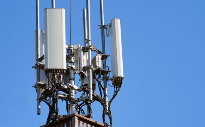
The customer is designing a satellite communication module. Because satellite communication equipment needs to accomplish high-performance RF signal transmission in limited space, the PCB solution should accommodate a compact design, consistent material performance, and long-term operational reliability.
We provided a PCB solution using RT/Duroid 5880 material and optimized the PCB stack-up structure with its properties. During manufacturing, we executed rigorous impedance control and verified the PCB’s performance through electrical inspections. Our design enabled the client to maintain impedance tolerance at ±5% and minimize high-frequency insertion loss and phase shift. The RF prototype successfully passed the satellite communication module’s performance tests.
Our Rogers PCB Material Datasheet
- Commercial High Frequency PCB Materials
- Low Loss Microwave PCB Materials
- High Dk RF PCB Materials
| Material | Dielectric Constant (Dk) | Dissipation Factor (Df) | Tg (°C) | Td (°C) | Operating Frequency | UL94 Rating | Fabrication Support | Typical Applications |
| RO4003C | 3.38 | 0.0027 | >280 | 425 | Up to 30 GHz | — | Pure Rogers & FR4 hybrid stackup | High-power RF systems and radar devices |
| RO4350B | 3.48 | 0.0037 | >280 | 390 | Up to 30 GHz | V-0 | 2–8 layers, blind & buried vias | Base station antennas and general RF designs |
| RO4835 | 3.48 | 0.0037 | >280 | 390 | Up to 30 GHz | V-0 | Enhanced copper foil adhesion | Designs requiring superior oxidation resistance |
| RO4360G2 | 6.15 | 0.0038 | >280 | 407 | Up to 30 GHz | V-0 | High-Dk controlled impedance | Power amplifiers demanding higher dielectric constant |
| Material | Dielectric Constant (Dk) | Dissipation Factor (Df) | Tg (°C) | Td (°C) | Operating Frequency | UL94 Rating | Fabrication Support | Typical Applications |
| RT/duroid 5880 | 2.20 | 0.0009 | — | 500 | Up to 110 GHz | V-0 | Thin core, tight dimensional tolerance | Millimeter-wave and ultra-high-frequency circuits |
| RO3003 | 3.00 | 0.0010 | — | 500 | 77 GHz and above | V-0 | Tight impedance control (±8%) | 77 GHz automotive radar sensor modules |
| RT/duroid 6002 | 2.94 | 0.0012 | — | 500 | Up to 40 GHz | V-0 | Multi-layer hybrid construction | Complex multi-layer aerospace and defense assemblies |
| Material | Dielectric Constant (Dk) | Dissipation Factor (Df) | Tg (°C) | Td (°C) | Operating Frequency | UL94 Rating | Fabrication Support | Typical Applications |
| RO3006 | 6.15 | 0.0020 | — | 500 | Up to 20 GHz | V-0 | Miniaturized layout support | Space-constrained RF component designs |
| RO3010 | 10.2 | 0.0022 | — | 500 | Up to 10 GHz | V-0 | High-Dk impedance matching | GPS antennas and compact power amplifier units |
| RT/duroid 6010.2LM | 10.2 | 0.0023 | — | 500 | Up to 10 GHz | V-0 | Temperature-stable Dk processing | Filters and couplers requiring Dk stability |
Consons Rogers PCB Manufacturing Process
We carefully control every step of the Rogers PCB manufacturing process to guarantee the authenticity of materials and meet the signal integrity standards of RF applications.
You May Also Be Interested In

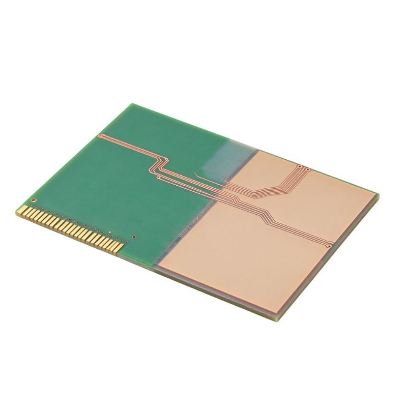
- Dielectric Performance: Rogers PCB materials offer more consistent Dk/Df characteristics, preserving reliable high-frequency performance, whereas FR-4 materials show greater variation in dielectric properties.
- Signal Integrity: Compared to FR-4, Rogers materials feature lower dielectric loss and better signal integrity in RF and microwave designs.
- Frequency Adaptability: Rogers PCBs are suitable for RF, microwave, 5G, and radar systems, while FR-4 is primarily used in standard electronic circuits.
- Cost: Because Rogers PCB materials have more advanced electrical properties, the material and processing costs are higher.
First, before choosing the proper Rogers PCB material, you need to determine the critical design parameters like operating frequency, signal loss range, and electrical performance targets.
Next, you should consider the characteristics of different materials, including dielectric constant, loss tangent, thermal stability, and impedance control capabilities. These data play an important role in the stability of your product’s signal.
Finally, different Rogers material series are suitable for varying requirements. The RO4000 series is commonly applied in RF and communications systems; the RO3000 series is ideal for radar and microwave devices; the RT/Duroid series is tailored for low-loss and high-frequency designs.
When your design requires operating frequencies exceeding 1 GHz, you can consider Rogers PCB materials. In high-frequency applications from a few GHz to tens of GHz, Rogers materials provide reliable dielectric properties and low-loss signal transmission, meeting the signal integrity, impedance control, and durability demands of high-frequency circuits.
For Rogers PCB manufacturing, the primary surface treatment processes are ENIG, ENEPIG, and immersion silver.
ENIG features a smooth surface, excellent oxidation resistance, and compatibility with fine-pitch components. It is a mainstream surface treatment process for Rogers PCBs. ENEPIG offers outstanding corrosion resistance and is widely used in aviation, aerospace, and advanced RF systems. The immersion silver process excels in electrical conductivity and is often employed in high-frequency designs that demand exceptional signal performance.
Additionally, these surface treatment processes protect the copper surface from oxidation and environmental corrosion. They help sustain the steady electrical properties of Rogers PCB materials.
Rogers PCBs have these copper foil types: ED copper foil, RTF copper foil, and RA copper foil. The choice of copper foil depends on your specific needs.
ED copper foil not only has great conductivity but is also quite affordable. It is used for standard high-frequency PCB applications.RTF copper foil undergoes surface treatment to enhance adhesion with dielectric materials while offering superior high-frequency performance, ideal for RF and microwave systems.RA copper foil provides outstanding flexibility and a smoother copper grain structure, perfectly suited for environments that require dynamic bending or high signal integrity.
The typical production lead time for our Rogers PCB manufacturing is influenced by material availability, board complexity, and production volume.
For standard Rogers PCB prototypes, the lead time is typically around 5–10 business days. For small-batch production, the lead time is approximately 2–3 weeks. For high-volume production, lead times may vary according to the number of layers and manufacturing demands, and this process could take 3–6 weeks.
If you require special materials, complex board structures, or customized manufacturing, the production lead time will extend accordingly.