



Why Choose Consons Relay PCB Board?
- Effective Thermal Management: Consons supports heavy-copper PCB layouts (up to 3 oz+), which help with effective heat dissipation. It provides sufficient current-carrying capacity for heavy-duty relay applications.
- High Voltage Safety: Strictly complies with high-voltage isolation standards. Precise slotting and creepage distance design make sure the safe clearance between the control circuit and the high-power switching contacts.
- Electrical and Functional Testing: Consons conducts 100% AOI and X-ray inspection of BGA and power components. We also provide customized functional circuit testing to verify relay activation and contact switching under real-load conditions.
- Wide Selection of Relay Types: We offer a wide range of relay PCB options, covering various relay types and contact configurations. They provide the flexibility to meet the needs of different applications, such as automotive electronics and smart home systems.
- Reliable Components: Consons only uses 100% original relays directly sourced from authorized distributors with CoC. We guarantee that every relay PCB is brand new and unused.
- Free DFM Review: Consons offers free DFM reviews to help you identify design flaws early on and improve production efficiency down the line.

What Is a Relay PCB?
A relay PCB is a printed circuit board specifically designed to mount one or more relays. It enables signal control, power switching, or load switching, and is widely used for switch control in various devices, such as washing machines, light fixtures, and heaters.
A relay PCB isolates the control circuit from the load circuit, allowing devices operating at higher voltages or currents to be controlled with only a small control signal. This provides greater safety and higher integration.
Send Consons your BOM and Gerber files. We will conduct a thorough evaluation of your relay PCB and provide you with a competitive quote.
Relay PCB Based on Relay Type

Uses an internal electromagnet to mechanically move physical contacts. Cost-effective and versatile, offers complete physical isolation and works well in general home appliance controls and basic industrial switching.

Semiconductor switching without mechanical contacts, quickly, silently, and without wear. Suitable for heating systems, lighting controls, automation equipment, and high-frequency industrial switching equipment.

Responds to current-induced heat for overload protection, providing reliable protection for motors, pumps, compressors, fans, and industrial control equipment under sustained electrical loads.

Combines mechanical contacts with semiconductor switching, achieving low conduction loss, fast response, and switching durability. Suitable for industrial automation, power controls, and high-reliability equipment.
Relay PCB Based on Contact Configuration
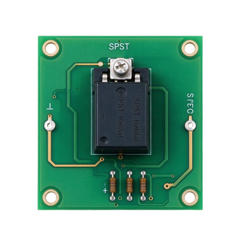
Provides simple single-circuit on/off switching through one pole and throw, offering compact control for lighting, heaters, power supplies, and basic industrial control equipment.
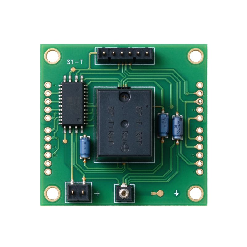
Switches one common circuit between two outputs, enabling flexible signal or load selection for motor control, automation systems, power routing, and mode switching.
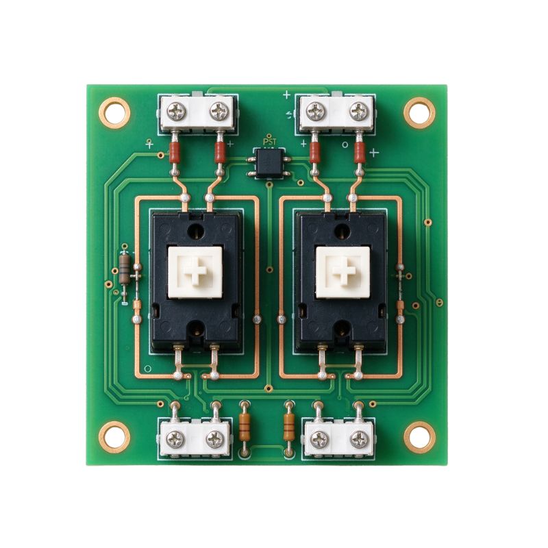
Configures two independent lines to be turned on/off simultaneously by one signal. Safely breaks both live and neutral lines at once, widely used in AC mains power switches.
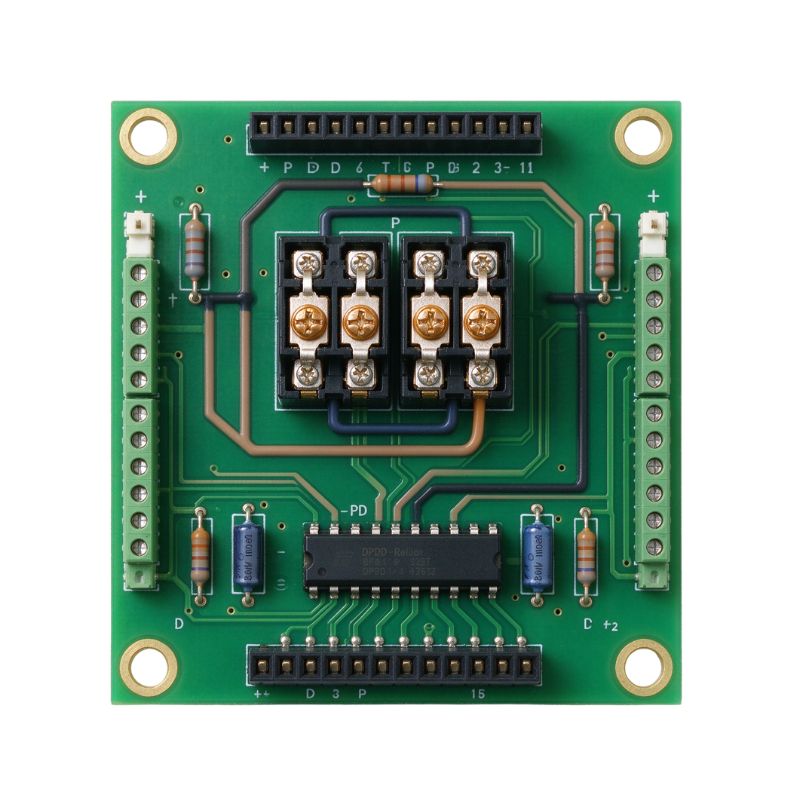
Switches two separate circuits between dual output paths. Offers maximum routing flexibility, widely used in polarity reversal, H-bridge motor drives, and complex signal routing systems.
Reliable Load Switching Performance
Consons relay PCBs are designed to handle high inrush currents and continuous heavy electrical loads without degradation. Through optimized heavy-copper traces and wide conductor spacing, our PCB maintains low contact resistance and minimal thermal dissipation during high-power switching. We also integrate creepage slots to prevent high-voltage electrical arcing between control lines and output contacts. Equipped with protection circuits to suppress high-voltage spikes and prevent contact welding, ensuring stable operation and long service life even under heavy AC/DC loads.

Secure Relay PCB Mount
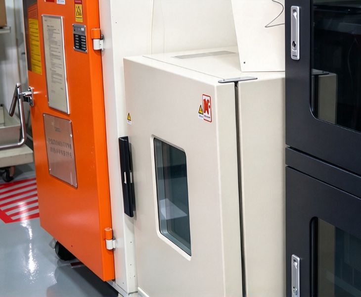
Consons offers relay PCB assembly services. With SMT placement tolerance within 0.025 mm, we can accurately mount small relay components, faithfully reproduce your design, and ensure reliable performance. For components that require THT mounting, we reinforce plated-through holes with thickened through-hole copper plating and enlarge solder pads to maximize mechanical joint strength. Over 75% solder barrel fill for heavy DIP pins, eliminating cold solder joints and pad cracking. Optional mechanical anchoring, component potting, or conformal coating further stabilizes heavy relay bodies. This provides long-term structural integrity in harsh, high-vibration operational environments.
Why Consons Is Your Reliable Partner?

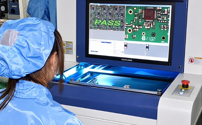
With 20 years of experience in PCB R&D and manufacturing, Consons provides professional ODM and OEM services. From prototype design to final assembly and testing of finished products, we offer a true one-stop service. Our client base includes leading brands across multiple sectors, such as consumer electronics, automotive, industrial control, and smart home, including Huawei, Porsche, and Siemens.
Consons sources electronic components and PCB materials from well-known brands such as Samsung, ROHM, Shengyi, and Avnet, and conducts 100% incoming inspection. Beyond using high-quality raw materials, we also achieve advanced manufacturing precision. Our rigid PCBs support a minimum line width/spacing of 3.5/4 mil, minimum mechanical drill size of 0.15 mm, 4 mil laser drilling, and a minimum annular ring of 4 mil.
Relay PCB Specifications
| Parameter | Specifications |
| Relay Type | Electromagnetic Relay, Solid-State Relay, Thermal Relay, Hybrid Relay |
| Contact Configuration | SPST, SPDT, DPST, DPDT |
| Relay Mounting | Through-Hole, SMT, Mixed Technology |
| PCB Structure | Single-Sided, Double-Sided, Multilayer |
| Number of Layers | 1–30 Layers |
| Base Materials | FR-4 and other application-specific PCB materials |
| Copper Thickness | Standard: 1/3–3 oz; Special Heavy Copper: up to 60 oz |
| Minimum Line Width / Spacing | 3.5 / 4 mil |
| Minimum Mechanical Drill | 0.15 mm |
| Minimum Laser Drill | 4 mil |
| Minimum Annular Ring | 4 mil |
| Relay Contact Rating | Customized according to selected relay and load requirements |
| Coil Voltage | Selected according to control circuit requirements |
| Switching Voltage | Customized according to relay and application requirements |
| Switching Current | Customized according to load and relay contact rating |
| Load Type | Resistive, Inductive, Capacitive and application-specific loads |
| Electrical Isolation | Control and load circuits designed according to application voltage and safety requirements |
| Creepage & Clearance | Designed according to working voltage, insulation requirements and applicable standards |
| Protection Circuits | Flyback Diode, TVS Diode, RC Snubber, MOV and other application-specific protection |
| Control Isolation | Optocoupler Isolation available according to circuit requirements |
| PCB Assembly | SMT, THT and Mixed-Technology Assembly |
| Relay Socket | Relay Socket mounting available for removable relay designs |
| Surface Finishes | ENIG, OSP, Lead-Free HASL, Immersion Tin/Silver and other supported finishes |
| Functional Testing | FCT (Functional Circuit Testing), including relay switching and circuit operation verification where applicable |
| Inspection | AOI and other inspection processes according to assembly requirements |
| Operating Temperature | Determined by relay components, PCB materials, and application requirements |
Project Case of Consons Relay PCBA

Riders often leave e-bikes outdoors in high humidity and rain. Frequent vibration on rough trails loosened traditional 12V relay PCB solder joints, causing sudden power loss and frequent customer complaints.
Consons redesigned the 12V relay PCB with extra-thick plated-through holes and added silicone potting around heavy relay legs. This reinforced anchoring system can withstand continuous off-road shaking. We also applied selective conformal coating to isolate the board from rain, dust, and coastal salt spray. These upgrades eliminated road-vibration failures, reduced field maintenance calls by 85%, and ensured reliable daily power switching for the client’s e-bikes.

Frequent compressor switching created strong electric arcing inside compact control cabinets. Standard boards suffered from heat accumulation and trace burning during peak summer operation, causing heat pump shutdowns.
Consons produced 3 oz heavy-copper PCBs with milled air isolation slots between control lines and 230V AC contact pins. The physical gap stopped arcing, while thick copper helped rapidly draw heat away from switching contacts. The customer reduced cabinet operating temperatures by 12°C and passed European CE safety tests.
You Can Use Our Relay PCB for:

Heavy factories demand zero downtime. Our Relay PCBs can manage high-power motor drives, robotic arm actuators, and PLC controllers, resisting severe electrical noise and vibration to keep assembly lines running safely around the clock.

Used for battery management, cooling fans, lighting, power windows, charging systems, and dashboard indicators. Relay PCBs handle compact layouts, vibration, temperature changes, and repeated switching in vehicle electronics.
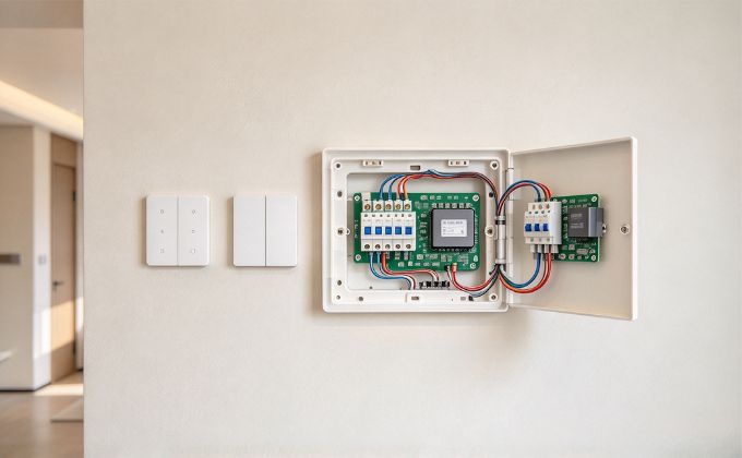
Modern living needs compact, quiet switching. Built for small spaces, relay PCBs can reliably operate smart wall light switches, air conditioner compressors, and motorized window blinds without annoying noise or overheating behind walls.
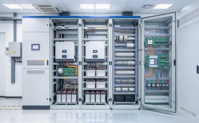
Relay PCBs support load isolation, protection control, and reliable switching under changing voltage and current conditions. They are suitable for managing circuit switching in UPS systems, inverters, battery storage, solar equipment, and power distribution units.
More Products

Integrated socket interface enables quick relay hot-swapping and electrical isolation, eliminating extra soldering to simplify maintenance inside industrial automation cabinets and power distribution boards.

Uses high glass-transition-temperature laminate for better dimensional stability and thermal resistance. Suitable for automotive electronics, power equipment, industrial controls, and high-temperature operating environments.
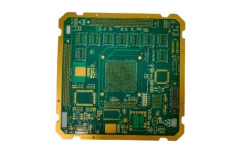
Combines component sourcing, PCB assembly, testing, and delivery under one service, simplifying procurement and quality control for complete electronic products, control boards, power systems, and industrial equipment.
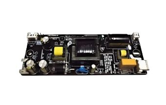
Testing of relay PCBs typically includes structural inspection and electrical functional verification. During the manufacturing process, Consons uses AOI and SPI to ensure that solder joints and component placement have no defects. Then in-circuit testing (ICT) is performed using a bed-of-nails fixture to detect open circuits and short circuits. For high-current and high-voltage applications, Hi-Pot testing and creepage distance verification are required. Finally, functional circuit testing simulates actual load conditions, and thermal Imaging monitors relay switching and temperature rise to help ensure consistent outgoing quality.
First, identify the load type, rated voltage, and maximum inrush current to determine the required copper weight and trace width. Next, consider the contact configuration and switching frequency to select the appropriate relay type. Regarding safety, it is essential to verify the creepage distance between high- and low-voltage areas and the design of the electrical isolation channel. You must account for environmental factors such as vibration resistance and corrosion resistance. Safety certifications such as UL and CE are also key factors in determining the circuit board material and protective processes.
A relay PCB is an electronic component that directly integrates relay elements and drive circuits onto a bare board. It is designed to work in conjunction with other motherboards. It offers high integration, low per-board cost, and a high degree of customization, making it suitable for high-volume embedded products.
A relay module is typically a finished product equipped with a protective housing, external terminal blocks, and DIN rail mounting brackets. It is ready for immediate use and offers a high level of protection, primarily used in field applications requiring rapid assembly, such as industrial control cabinets.
Consons offers flexible MOQ. We support orders from single-piece prototyping to mass production. Even for a single-board prototype, we provide consistent, professional DFM evaluation and assembly services. Consons will help you reduce early-stage R&D costs and smoothly transition to high-efficiency, large-scale production lines as your business grows.
The load type directly affects the relay PCB protection topology and copper current-carrying design. For resistive loads, the design should focus on steady-state temperature rise and standard trace design. For inductive loads, such as motors and solenoid valves, power-off can generate high back-EMF. A flyback diode or RC snubber is required to reduce contact arcing. Capacitive loads create high Inrush Current at startup. Wider traces and anti-welding contacts may be needed.
The trace width for high-current applications is primarily determined based on the IPC-2221 standard, taking into account the maximum continuous current, allowable temperature rise, and copper foil thickness. You can set the target temperature rise and calculate the required conductor cross-sectional area. If the board width cannot meet the requirements, the current-carrying capacity can be enhanced through processes such as increasing the copper thickness on the back side, creating solder mask openings, or soldering on thickened copper strips. Additionally, A safety margin of at least 20% must be allowed to account for sudden overcurrent events.
To improve switching reliability and extend contact life, relay PCBs often integrate various protection circuits. The coil side typically uses a flyback diode or TVS diode to absorb reverse inductive voltage when the coil is switched off. The contact side often uses an RC snubber or MOV to reduce high-voltage arcing and surge impact. Optocoupler Isolation is also commonly used on the control signal side to prevent noise from the high-power circuit from affecting the upstream MCU.