



Your Rigid-Flex PCB Manufacturer in China
- Layer Capability: 2–30 layers for complex rigid-flex PCB designs.
- Line Width/Spacing: Minimum 3/3 mil for high-density routing.
- Drill Capability: 3 mil laser drilling and 0.1 mm mechanical drilling.
- Impedance Control: ±10% tolerance for high-speed and high-frequency signals.
- Copper Thickness: 1/3–1 oz in flexible areas, with customizable rigid-area copper thickness.
- Certification: ISO 9001, ISO 14001, IATF 16949, UL, RoHS, and REACH compliance.
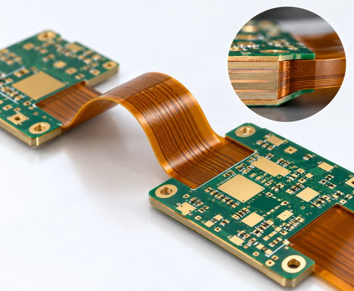
What Is A Rigid Flex PCB?
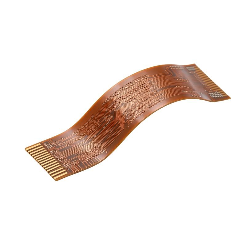
Rigid flex PCBs integrate rigid and flexible PCBs into a uniform structure, simultaneously providing mechanical support and flexible connections. The rigid areas offer structural stability, while the flexible areas support 3D routing and spatial adaptation, minimizing traditional connectors and wiring harnesses.
Consons has mature rigid flex PCB manufacturing processes, rigid-flex laminate design capabilities, and precision machining technology. We can provide you with a one-stop rigid flex PCB solution to help you simplify the PCB development process and accelerate product delivery.
Types of Rigid Flex PCB Consons Manufactured

Composed of a combination of single-layer flexible circuits and rigid sections, which can reduce the number of connectors and simplify assembly.

Double-sided conductor designs provide more routing space than single-sided structures, supporting complex circuit connection requirements.

By integrating multilayer rigid PCBs and multilayer flexible PCBs, achieving complex circuits, high-density interconnects, and 3D routing.
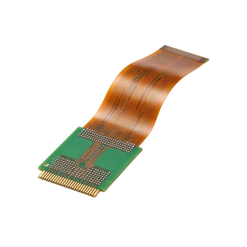
Supports miniaturized design and is able to expand routing capability and improve signal integrity, realizing smaller, lighter, and more complex product designs.
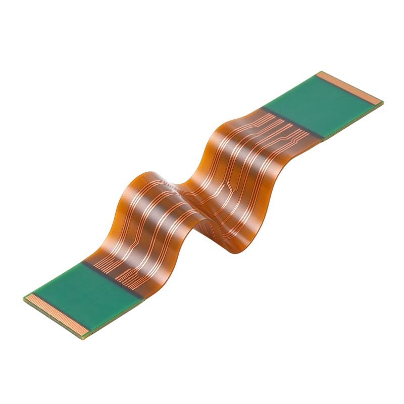
Designed for applications requiring repeated bending motions, the flexible sections can withstand long-term mechanical cycles, lowering maintenance costs.

Employing a stepped structural layout similar to book page turns can optimize the 3D spatial layout and improve assembly flexibility.
Advantages of Rigid Flex PCB

The 3D routing combined with a lightweight design makes the PCB accommodate complex product structures and compact installation spaces.

Minimizing signal loss and impedance variations from traditional connectors and wiring harnesses enhances the stability of high-speed signal transmission.

Utilizes optimized flexible materials, copper foil selection, and laminate design to improve
bend resistance, suitable for high-vibration and extreme temperature environments.

Integrating multiple PCBs, connectors, and wire harnesses into a single rigid flex structure can simplify assembly and improve manufacturing efficiency.
Multiple Material Options for Different Applications
Consons offers multiple material combinations used in the manufacture of rigid flex PCBs, including Shengyi and Panasonic Megtron high-Tg FR-4 rigid substrates, Taiflex FCCL, DuPont Pyralux polyimide flexible cores, RA/ED copper foil, low-flow prepregs, and flexible soldermask. We can provide you with the optimal material combination aligned with your bending demands, thermal conditions, and product specifications. This will give you a cost-effective combination of materials.
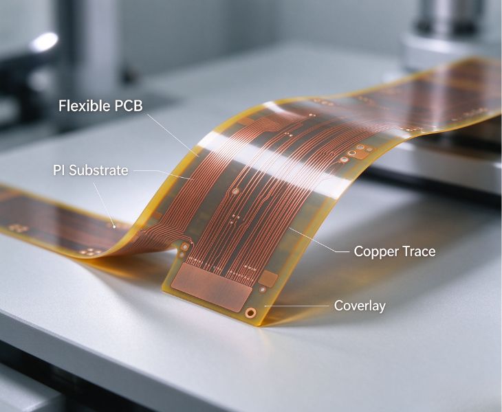
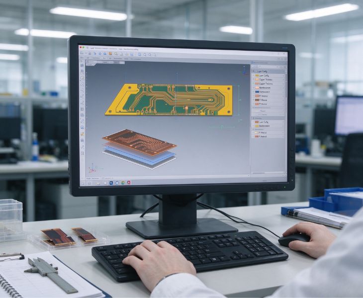
Optimized Stack-up Design for Reliable Rigid-Flex Integration
Conson provides customized rigid flex PCB stack-up structures for various applications. Through properly arranging the layout of interlayer structures and transition zones, we accomplish complex spatial mounting and high-reliability design demands. Our engineering team also supports the development of multilayer rigid flex structures. We can assess manufacturing feasibility through DFM reviews to help you smoothly complete the entire process from design to production.
Why Choose Consons As Your Rigid Flex PCB Partner?


Proven Manufacturing Expertise
We have over 20 years of experience manufacturing rigid flex PCBs and are very familiar with the production standards and requirements of different industries.
Full‑range Quality Control
Every rigid flex PCB will undergo AOI inspection, electrical testing, impedance testing, and visual inspection to verify that your received product is consistent.
Free DFM Review
Before the project begins, we’ll provide a free DFM review to help you avoid manufacturing hazards and minimize revision risks.
Reliable After‑sales Support
We provide sustained technical support and project follow-up services. If you encounter any issues, please contact us promptly.
Our Rigid Flex PCB Specification
| Technical Parameter | Standard Capability | Advanced Capability |
| Max Layer Count | 2–12 Layers (up to 8 flex layers) | 13–20+ Layers (Subject to Stack-Up DFM) |
| Min. Trace / Space (Rigid Zone) | 3.5 / 3.5 mil (88 / 88 µm) | 3.0 / 3.0 mil (75 / 75 µm) |
| Min. Trace / Space (Flex Zone) | 2.0 / 2.0 mil (50 / 50 µm @ 1/3 oz Cu) | 1.5 / 1.5 mil (38 / 38 µm, DFM required) |
| Min. Mechanical Drill Size | 0.15 mm (6 mil) | 0.10 mm (4 mil) |
| Min. Laser Microvia Size | 0.10 mm (4 mil) | 0.075 mm (3 mil) |
| Rigid-Flex Board Thickness | 0.4 mm – 3.0 mm | 0.3 mm – 4.5 mm (subject to stack-up design) |
| Max Base Copper (Rigid Zone) | 2 oz | 3 oz |
| Max Finished Copper (Rigid Zone) | 3 oz | 4 oz |
| Max Base Copper (Flex Zone) | 1 oz | 1 oz |
| Max Finished Copper (Flex Zone) | 2 oz | 2 oz |
| Aspect Ratio (Mechanical Drill) | 10:1 | 12:1 |
| Aspect Ratio (Laser Microvia) | 0.7:1 | 0.8:1 |
| PTH / NPTH Tolerance | PTH: ±0.05 mm; NPTH: +0 / –0.05 mm | Tighter tolerance via special process control |
| Outline & Cutout Tolerance | ±0.10 mm (±4 mil) | ±0.075 mm (±3 mil) |
| Impedance Control Tolerance | ±10% | ±5% |
| Max Panel Size | 406 mm × 610 mm | 406 mm × 610 mm |
| Min. Board Size | 6 mm × 6 mm | 6 mm × 6 mm |
| Surface Finishes | ENIG, Immersion Silver, Immersion Tin, OSP | ENEPIG, Hard Gold (Gold Finger), Selective ENIG + OSP |
Where Are Consons’ Rigid Flex PCBs Applied?

Our rigid flex PCBs work well in medical imaging equipment, patient monitoring devices, and surgical instruments. They can replace traditional wiring harnesses and connectors, reduce internal space occupation, and meet the long-term stable operation needs.

ADAS systems, vehicle control modules, battery management systems, and others can use our rigid-flex PCBs. These circuit boards offer excellent vibration resistance and heat resistance and support high-speed signal transmission.

The rigid flex PCBs can also be used in PLC systems, robotic equipment, and industrial sensors. Our 3D routing structure decreases the number of connectors and wiring harnesses required, helping to minimize interference during signal transmission and improve system stability.

Consumer products tend to have a design that is both small and lightweight. Our rigid flex PCBs utilize the bending capability of the flexible sections to achieve 3D routing in complex spaces, reducing additional connectors and lowering overall weight. Ideal for wearable electronics, foldable devices, and smart devices.

Our rigid flex PCBs are designed for drone electronics, avionics systems, and aerospace control modules. Their lightweight design and robust mechanical performance meet the demands of steady operation in the harsh environments of aerospace.

This equipment has rigorous standards for signal transmission and integrity. We employ HDI structures, microvia technology, and impedance-controlled designs to accomplish high-density interconnects and high-speed signal transmission, which are tailored for network equipment, RF modules, wireless devices, and related products.
Project Cases of Consons Rigid Flex PCB

The customer required a 6-layer rigid flex PCB for a compact electronic module. The traditional rigid PCB solution had to connect the module with multiple connectors and wire harnesses. This not only adds to assembly complexity but also makes the rigid-flex transition area prone to stress concentration.
For this project, we implemented an air-gap construction, low-modulus adhesive selection, and stress relief structure optimization in the rigid-flex transition area. This solution decreases mechanical stress by approximately 30%, minimizes external connector and wiring harness requirements, and improves internal module space utilization by roughly 15%.

This customer needs a rigid flex PCB that can withstand long-term repeated bending in high-speed automated applications. Regular flex PCBs easily suffer from copper foil fatigue, circuit cracking, and degraded electrical performance in high-frequency and dynamic environments.
We optimized the materials and stack-up structure of the flexible sections to match the product’s movement direction, bend radius, and rate of use. By selecting appropriate PI materials, copper foil specifications, and flexible layer layouts, we enhanced the durability of the bending areas, enabling the PCB to withstand over 100,000 dynamic bends and sustain consistent electrical connections.
Consons Rigid Flex PCB Manufacturing Process
Every step of our rigid flex PCB manufacturing process strictly adheres to the corresponding quality inspection procedures to guarantee that the products you receive have no abnormal quality issues.
You May Also Be Interested In


Before starting rigid flex PCB production, we usually require these important documents.
- Gerber: Contains design data of each rigid and flexible layer, like routing, solder mask, silkscreen, and polyimide coverlay details;
- Drill Files: Provide the positions and dimensional parameters for through-holes, blind vias, buried vias, and holes in the rigid-flex transition areas.
- PCB Manufacturing Specifications: Include the layer stack-up, rigid-flex partition boundaries, board thickness, copper thickness, surface finish, and material requirements;
- BOM and Assembly Documents (for PCBA projects): Used to confirm the component procurement and assembly needs of the rigid flex PCB.
The minimum bend radius of our rigid flex PCBs depends on the thickness of flexible sections, material selection, copper thickness, and bending applications. Generally, static bending requires a bend radius of approximately 5–10 times the flexible board’s thickness. Dynamic bending needs a bend radius more than 10 times the thickness to guarantee long-term durability.
The bend life cycle of our rigid flex PCBs is affected by the flexible material, copper foil type, stack-up configuration, and the operational environment.
For static applications, rigid flex PCBs are commonly subjected to bending during the installation process; In dynamic conditions, a properly designed rigid flex PCB can typically withstand over 100,000 bending cycles under standard test conditions. Additionally, we strive to sustain dependable performance across the product’s entire lifecycle by carefully choosing the materials, stack-up optimization, and mechanical stress control.
Yes. We can help you achieve high-density interconnects in rigid flex PCBs by utilizing laser-drilled microvias, fine traces, and advanced laminate designs. We can also develop HDI designs combined with blind vias, microvias, and complex rigid-flex laminate structures. In addition, our engineering team provides DFM reviews to optimize your via structures, interlayer connections, and signal performance, enabling a smooth volume production process.
- Structure: Rigid flex PCBs are laminated using rigid and flexible PI substrates, combining rigid areas and bendable flexible areas; rigid PCBs are made with rigid insulating substrates and cannot be bent.
- Circuit Complexity: Rigid flex PCBs can realize cross-region routing, meeting demands of high-density trace layout and dynamic bending; rigid PCBs support high-density circuits without bending capability.
- Space Utilization: Rigid flex PCBs enable 3D assembly through bending, reducing the space occupied inside the device; rigid PCBs can only be installed in a flat configuration and are limited by the space of the product enclosure.