

A PCB (Printed Circuit Board) is a fundamental component in electronic devices used to mount and support electronic components. This article will introduce common circuit board components, including their basic functions, testing methods, and considerations when selecting and replacing components.
What Components Are on a PCB?
There are many parts of a PCB, each of which plays a specific role in making up the PCB.
Resistor
Resistors (R) are common circuit board components on PCBs, primarily used to limit and control current, as well as for voltage division and signal level adjustment. The unit of resistance is the ohm (Ω), and the resistance value affects the magnitude of the current at a given voltage.
Based on their application and structure, resistors are typically classified into fixed resistors, variable resistors, and special-purpose resistors.
- Fixed resistors include carbon-film, metal-film, metal-oxide, and wire-wound resistors.
- Variable resistors include potentiometers, rheostats, and trimmers.
- Special-purpose resistors include thermistors, photoresistors, and varistors.
On a PCB, axial resistors—which are the most common type—typically have leads at both ends and colored bands on their surface. These color bands indicate the resistance value. SMD resistors are usually identified by numerical codes on their surface. Resistors can be used to control light brightness and motor speed, and they can also be combined with capacitors to form filters and amplifiers.
Capacitor
A capacitor (C) is a passive component that can store and release electrical energy. It is commonly used for filtering, signal coupling, and voltage stabilization.
Capacitors store energy through an electric field. Their basic structure consists of two conductive plates and a dielectric material in between; the unit of capacitance is the farad (F). Depending on their structure and materials, common types include ceramic capacitors and polymer capacitors, among others.
Different types of capacitors are suited for different applications.
- Ceramic capacitors are suited for high-frequency applications.
- Electrolytic capacitors typically have a large capacitance and are polarized.
- Film capacitors are characterized by their stability and low distortion.
- Tantalum capacitors are characterized by their small size and high capacitance.
Common radial capacitors have two leads extending from the same end. In actual circuits, capacitors can be combined with resistors to form filters. You can also use them directly for power supply energy storage and to block DC signals.
Inductor
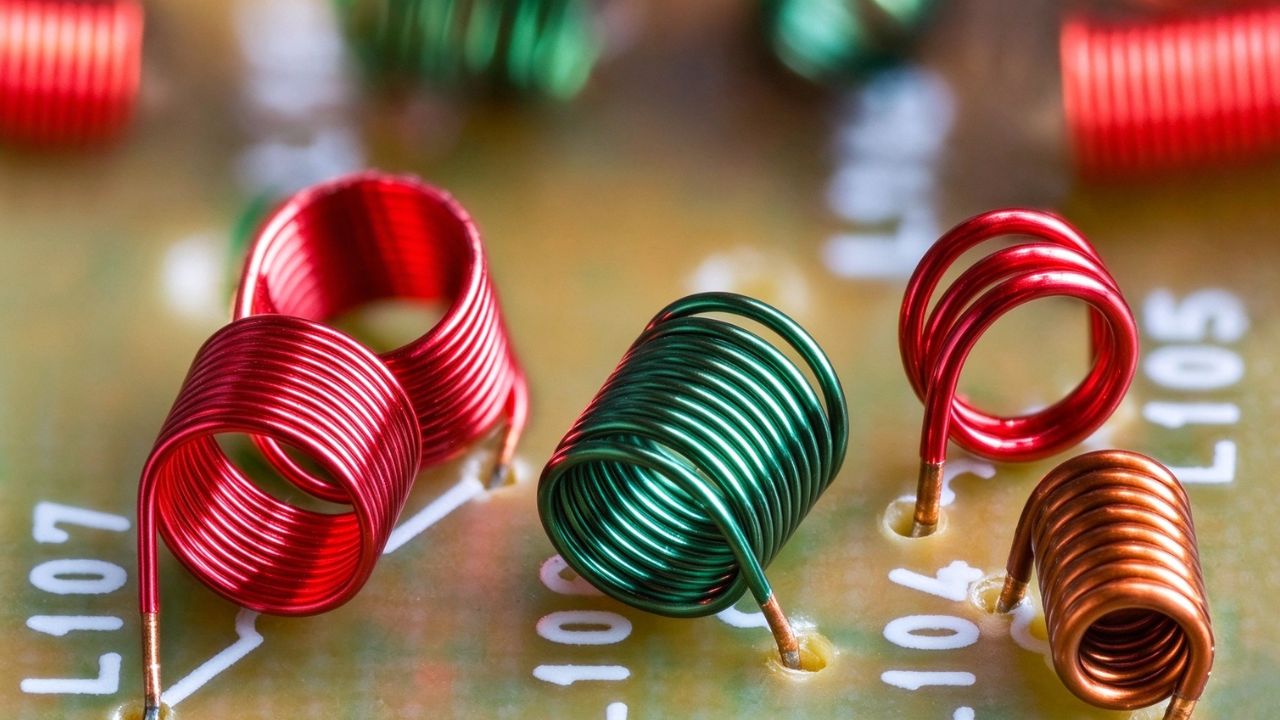
An inductor is a linear passive component and, like resistors and capacitors, belongs to the category of passive components. It primarily stores energy using a magnetic field, and its basic structure is typically a coil; some inductors also incorporate a magnetic core to strengthen the magnetic field.
The unit of inductance is the henry (H), and its value is influenced by factors such as the number of coil turns, the coil’s cross-sectional area, and the material of the magnetic core. Generally, the more turns in a coil, the higher the inductance value. When the current changes, the inductor generates an induced voltage in the opposite direction of the current change; this phenomenon is called self-inductance.
Common types of inductors include air-core inductors, ferrite-core inductors, and others. You can find them in circuits such as filters, and inductors can also be used for energy storage.
Diode and LED
Diodes and LEDs (D) primarily operate based on their unidirectional current-conducting properties and can be used for rectification, reverse-polarity protection, and status indication. Diodes are semiconductor devices that, under normal conditions, allow current to flow from the anode to the cathode and block reverse current.
Common types include silicon diodes, Zener diodes, LEDs, and Schottky diodes.
- The forward voltage drop of a typical silicon diode is approximately 0.7 V.
- Zener diodes are primarily used for voltage regulation.
- Schottky diodes feature a lower forward voltage drop and faster switching speeds.
- LEDs are used for light emission and display purposes.
Diodes can be used in circuits such as rectifiers. Since LEDs are a type of diode, special attention must be paid to their polarity during installation. For diodes on a PCB, the cathode direction can also be determined by the stripes on the component.
Transistor
A transistor (Q) is a semiconductor active device and one of the basic building blocks of modern electronic devices. It can amplify or switch electronic signals and electrical power, and is also commonly used for current control.
Common types of transistors include BJTs and FETs. BJTs are further classified into NPN and PNP types; they have three terminals—base, collector, and emitter—and can control large currents with relatively small input signals.
FETs, on the other hand, control circuits via an electric field; common types include JFETs, MOSFETs, and Darlington transistors.
In actual PCB circuits, transistors can be used for functions such as signal amplification and oscillation.
Integrated Circuit (IC)
Integrated circuits (ICs) integrate a large number of circuits and components onto a semiconductor wafer, enabling multiple circuit functions to be implemented on a single chip. Compared to using a large number of discrete components separately, ICs can consolidate complex functions into a single device and are therefore often critical components of large electronic systems.
Integrated circuits can perform complex functions such as logic operations and arithmetic. ICs commonly found on PCBs typically come in black plastic packages and can be connected to the PCB via leads or BGA pads.
Connector
Connectors (J/CN) are primarily used to establish electrical connections between a PCB and a cable or another circuit board. Connectors allow you to connect a PCB to external circuits or other devices, and they also facilitate subsequent installation and connection.
Switch

Switches control current by changing the circuit’s open or closed state, thereby enabling the circuit to be turned on or off.
Common types of switches include slide switches, rotary switches, push-button switches, and key switches. Different types of switches have different operating methods; you can choose the one that best suits your specific control needs.
Relay
A relay is a type of electromagnetic switch that uses the electromagnetic force generated by a solenoid to control switching operations. One of its common functions is to use a relatively small current to control a larger current or a high-voltage load.
Therefore, relays are commonly used in circuits where a low-power signal is needed to control a higher current or voltage load.
Transformer
A transformer uses magnetic coupling to transfer electrical energy from one circuit to another, enabling either boosting or stepping down the voltage. It also provides electrical isolation and impedance matching.
A transformer typically consists of a soft-iron core and at least two sets of windings. The side connected to the power source is called the primary winding, while the other side is the secondary winding. The secondary winding is responsible for transferring energy to the other circuit.
SCR / THY
An SCR/THY is a silicon-controlled rectifier, also known as a thyristor, and is a semiconductor device used for power control. It has three terminals and consists of four layers of silicon; in essence, it functions similarly to two transistors working in tandem.
SCRs are primarily used for switching rather than signal amplification. They require only a single pulse to trigger, making them better suited for switching higher power levels; they are mainly used in high-power AC/DC control and rectification.
Crystal Oscillator
A crystal oscillator generates periodic electronic signals through the mechanical vibration of piezoelectric material, providing a clock signal for circuits.
It is characterized by its compact size and is used in devices such as quartz watches.
Potentiometer
A potentiometer is a type of resistor, classified into rotary and linear types. It changes the resistance value by moving the slider contact, thereby allowing you to adjust circuit parameters.
Rotary potentiometers are commonly used for volume control in radios. Linear potentiometers, on the other hand, are suitable for adjusting and finely tuning settings on the spot.
Sensor
Sensors are used to detect changes in conditions and convert the detected phenomena into corresponding electrical signals. They are essentially transducers.
Common conditions include temperature sensors, humidity sensors, light sensors, and motion sensors, among others.
How to Identify PCB Components and Verify Them?

When performing circuit board component identification, do not only rely on their appearance. For components that look similar, it is easy to make mistakes based on appearance. A better method is to verify them by checking reference designators and part numbers.
First, you can identify components on a circuit board by using the reference designator.
- R stands for resistor
- C stands for capacitor
- D stands for diode
- Q stands for transistor
- U/IC stands for integrated circuit
- J/CN stands for connector
- SW stands for switch
- K stands for relay
- T stands for transformer.
Next, examine the component’s appearance and package type. SMD components are mounted directly onto the PCB surface, while DIP or other through-hole packages are mounted through holes in the PCB. Different package types can help you narrow the selection.
The markings on the component’s surface are also important. You can identify the resistance value of a resistor by its color bands or SMD numeric code; markings on a capacitor help make sure its capacitance. And the stripe on a diode can be used to determine the cathode direction.
If you need to confirm a model, you can check the part number, manufacturer’s markings, and data sheet. This step is especially important for unmarked ICs or three-pin components that look similar. Transistors and voltage regulators, for example, can be easily confused because they use similar three-pin packages.
When possible, you can also verify the components by cross-referencing schematics, BOMs, and actual measurement results. Tools such as digital multimeters and LCR meters help confirm the actual parameters of the components. Online databases or AI tools can be used as identification methods, but they cannot replace data sheets and actual testing.
Following this approach, you can first determine the approximate type of component and then confirm the model and parameters. This step is important for subsequent PCB testing, troubleshooting, or component replacement.
How to Choose Common Circuit Board Components?

Package type is a factor that cannot be ignored when selecting components.
If PCB space is limited, component size and package type must be considered in advance. The complexity of the PCB and the space required will also affect the number of copper layers. Multilayer PCBs can utilize different copper layers to route power, ground, and signal lines.
During actual layout, you must also consider component size, board space, trace length, and signal interference. Components cannot simply be placed “wherever they fit”; improper placement may also affect subsequent routing and circuit performance.
Be sure to verify the orientation of polarized components. Components such as diodes, electrolytic capacitors, and ICs all have specific polarity or orientation requirements. The stripe on a diode helps you identify the cathode direction, and you must also verify the polarity when installing LEDs. Electrolytic capacitors are also polarized and must not be installed in the reverse direction.
PCB Component Replacement
If a component on the circuit board is damaged and needs to be replaced, first turn off the power and allow the circuit to discharge completely before proceeding. Common tools include a soldering iron, a desoldering pump, desoldering wire, a hot-air rework station, flux, tweezers, and a PCB holder.
When removing a component, first melt the solder at the joint, then use a desoldering pump or desoldering wire to remove the solder, and gently lift the component out. Do not pull forcefully during this process, as this can easily damage the PCB pads.
Before installing a new component, verify its part number, package type, and mounting orientation. If the component is polarized, ensure it is oriented correctly. When soldering, use flux and carefully control the soldering temperature and duration.
Excessive heat or prolonged exposure can damage the component or even cause the PCB pads to warp.
After completing the replacement, it is also important to inspect the quality of the solder joints. Ensure that the component is securely mounted, the solder joints are sound, and there are no obvious soldering issues before proceeding with further testing.
FAQ
What Is a Circuit Board Components List?
A circuit board components list is typically a BOM (Bill of Materials) that records the components required to build a PCB assembly. It may include part numbers, quantities, package information, manufacturers, and other procurement or assembly details.
How to Test Circuit Board Components?
The testing method depends on the component. A digital multimeter can be used for basic checks such as resistance, continuity, diode forward voltage, and voltage measurements, while an LCR meter can measure parameters such as capacitance and inductance. For ICs and other complex components, testing may require circuit diagrams, specialized test equipment, or comparison with a known-good board.
How to Safely Repair PCBs?
Before repairing a PCB, disconnect the power supply and make sure the capacitors have been fully discharged. Ensure good ventilation while soldering; use a fume extractor if possible, and wear safety goggles. After use, place the soldering iron on a stable, heat-resistant surface to avoid burns or other safety hazards.
Why Doesn’t The Circuit Board Work Properly Even After Replacing The PCB Components?
It isn’t necessarily a problem with the new components themselves. First, check whether the components are installed in the wrong orientation and whether there are any cold solder joints, poor solder joints, or solder bridges. Also, check to see if the PCB pads or traces were damaged during the desoldering process. If everything appears normal, proceed to measure the voltage or other parameters of the relevant circuit.
When Should You Replace PCB Components Instead Of Continuing To Repair Them?
If a component is visibly burned out or its specifications deviate significantly, you should consider replacing it. For components with damaged internal structures, if the repair is difficult or carries high risks, you should conduct a comprehensive assessment of whether the repair is worthwhile, rather than focusing solely on the price of a single component.
Final Thought
Every component on a PCB affects the board’s proper operation. Understanding the functions and characteristics of these common circuit board components is the foundation of PCB design and assembly. If you’re looking for solutions related to PCB assembly and design, please feel free to contact CONSONS. We offer one-stop solutions.